Saturday, December 3, 2011

A TDR scope

I've gone and bought an old oscilloscope, a Tektronix 11801B.  The 11801 is a 20 year old design, but it still has some pretty impressive specifications: 50GHz analog bandwidth and takes a sample in 10fs (yes, femtoseconds).  With the scope I got a SD-24 sampling module which only has 20GHz bandwidth but it also has a pulse generator to make TDR measurements.

So what is TDR?  It is an acronym for "Time Domain Reflectometry".  What it means is that the scope generates a really fast voltage pulse into a cable and at the same time it is sampling the voltage at the source and showing how the voltage changes over time.  With an infinitely long perfect cable the pulse will travel along the cable forever, but in many cases there are imperfections in the cable that reflect the pulse back to the source and change the shape of the signal seen there. 

There are lots of articles about TDR out there, just google a bit and you'll find a lot of information.  I will just write a bit of what I can measure with my scope.


The SD-24 module has a SMA connector on the front.  If I leave that connector open, the pulse travels from the generator, and reaches the connector.  Since there is nothing there is looks like an infinite resistance so the pulse has nowhere to go and is reflected back.  The reflected pulse is added to the outgoing pulse which doubles the voltage.  This is how it looks at the scope.
Open circuit
The step on the left is the pulse generated by the scope and the step in the middle is the reflection.  I have told the scope to grade the horizontal axis in meters, so the scope tells me that Δm, the distance the pulse has travelled, is about 77.6mm.  Since the pulse has travelled to the connector and back again, the length of the cable between the source and the connector is half of that, Δm/2, which is 38.8mm.  Actually, the scope always measures time, the time between the two steps is about 370ps and assuming that the signal travels at 70% of the speed of light in the cable, the scope calculates that the distance travelled is 370E-2 * 300E6 * 70% = 77.6mm.

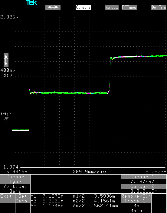
If I instead short the output, the pulse is shorted to ground at the end and the voltage of the reflected pulse is inverted, so the sum of the outgoing pulse and the reflected pulse is zero.
Short circuit
Note that the measured length of the cable is slightly longer, which is quite correct since the shorting plug I added to the end of the connector sticks out a bit so the signal has to travel a slightly longer distance.

There are no cables with infinite length, but it is possible to fake it by terminating a cable with a resistor having the same resistance as the characteristic impedance of the cable. Most oscilloscopes and coaxial cables used in a lab have a characteristic impedance of 50Ω, so putting a matching 50Ω terminating resistor at the end will absorb the pulse and there will be no reflection at all.
50Ω termination
Note that there is a bit of a bulge where the terminator is because the SMA connector on the scope or the terminator doesn't have a perfect 50Ω impedance. With a perfect termination there would just be a flat line, but there are no perfect terminators either.

If the termination resistor is larger than 50Ω there will be a positive reflected pulse, but the voltage of the pulse will be less than with an open circuit.  Here the output is terminated with a 100Ω resistor.
100Ω termination
The measured impedance of the cable inside the scope, ρ1, is about 50.20Ω and the measured impedance of the terminating resistor, ρ2, is 99.25Ω.  Pretty good eh?

Similarly, with a smaller terminating resistance there will be a smaller inverted reflected pulse.
25Ω termination
The measured impedance of the terminating resistor is 25.87Ω.

It is quite important to tighten the SMA connectors properly.  This is how the signal looks with the same 50Ω terminator when it hasn't been properly tightened.  Because there isn't a proper connection the impedance becomes higher and a rather big reflection is generated, the measured impedance is 77.87Ω which is quite a lot.
Improperly tightened 50Ω terminator

One of the more practical uses of TDR is to measure the distance to a short or open circuit on cables.  If I attach a matched 50cm long coaxial cable to the connector on the scope, the pulse will travel to the end of the cable before being reflected back. The end of this cable was left open, so the same reflection as with the open port is seen, just delayed a lot.
50cm of coaxial cable
The measured length, which includes the cable inside the scope, is 562mm which matches reality fairly well: about 40mm of cable inside the scope and another 500mm of coaxial cable outside.  The measured length depends on the propagation speed of electricity in the specific kind of coaxial cable used, but normally it's around 70% of the speed of light.  With the exact propagation speed for a certain cable it is possible to get a much better distance measurement.

This kind of measurement is really useful when trying to figure out where a 1000 meter long buried cable has been damaged.  With TDR it's possible to measure the distance to the cut (or short circuit) with a good resolution, so the technicians trying to repair the cable will know exactly where to dig.

Imperfections on the cable will also show up as impedance changes and cause reflections.  This is how a cable looks when it is being pinched hard.
Pinched coaxial cable
Because the shield comes closer to the center conductor when pinched, the impedance becomes smaller.  It's not extremely bad, only 10% difference in impedance, but if this was a TV antenna, this could show up as a ghost image on the screen.  In a high speed digital communications system, the reflection could be bad enough to corrupt data, or at least slow down transmission because a packet of data has to be resent.  TDR can be used to find this kind of imperfections in a 1000 meter cable too.

Sunday, November 27, 2011

SD Sniffer part 2

I've finally had time to play around a bit more with the SD sniffer I designed a few weeks ago.  I started placing all the active components on the board and also got to curse myself for choosing the tiny, tiny, SC70 packages for the comparators.  The SC70 package is tiny and the components  were quite tricky to solder, mostly because I don't have access to a stereo microscope any more.  But it all worked out in the end.

Since I have used the OpalKelly FPGA board before and have a lot of existing code for it, it didn't take long to hack together an FPGA image that could control the D/A converter on the board to set the reference voltage for the comparators.  With that done it was possible to probe the outputs from the comparators with a scope and see that the signals matched the signals on the SD bus.  One of the purposes with this board was to not put too much load on the SD data lines, and this actually seems to work.  I have a high speed SD card which runs at 48MHz which gets a lot of errors if I probe the CLK line with a normal 10x scope probe.  With the sniffer board it works fine at 48MHz without any errors.

A little while later I could actually get the signals into the FPGA and then stream them onto my PC.  The current FPGA image is rather simple, on every SD CLK edge it samples the SD CMD and SD DATA lines and stores them in a FIFO buffer inside the FPGA.  The Cypress FX2 USB controller on the OpalKelly board then streams the data from the FIFO to the PC.   This is basically what the USBee does, so this has the same limitation of 30MHz clock speed on the bus.  So the only advantage so far is that my SD sniffer doesn't affect the SD bus signals as much as the USBee does.

But since I have access to the FPGA on the OpalKelly board there's a lot more that can be done.  The USBee wastes a fair bit of the USB bandwidth since it always transfers 8 bits to the host for each sample.  The SD bus only uses 5 bits per sample, the CMD line and four DATA lines, so 3 out of every 8 bits going over the USB bus are unused.  With the FPGA it's quite simple to pack eight 5 bit samples into five 8 bit words.  So to be able to handle a 50MHz bus it needs 50*5/8 = 31.25MBit/s throughput on the USB bus which is just about what's possible.

But first I'll clean up the existing code a bit and then start working on some way of processing and presenting the raw SD bus data.

Tuesday, November 15, 2011

SD Sniffer

I need to debug a problem with a SD bus.  I have previously used a USBee SX with a custom firmware to sniff the bus and save a trace of all the SD signals to the hard drive so I could analyse them offline.  This works fine up to about 30MHz but then the USBee runs out of bandwidth to the host PC.  But the SD standard version 2 allows the bus to run at up to 50MHz and also tightens the electrical requirements for the SD bus, limiting impedance and capacitance so that the bus reliably can run at such high speeds.  So for modern cards the USBee can't keep up and the long wires to the USBee can introduce a bit too much loading and deteriorate the signals so much that the SD card will no longer work.

So I decided to build an adapter card which has a bunch of high impedance comparators sitting very close to the SD bus wires so that I can sniff the bus while changing the signals as little as possible.  The signals will then be fed into an OpalKelly XEM3001 FPGA Board that I happen to have lying around.  Anyway, since I have lost the source code that I used before to do the sniffing and analysis I have to rewrite everything anyway, so why not get a bit overambitious, I mean, what's the fun in doing the same thing over again?

Time to fire up Eagle and throw together some schematics.  The SD bus is available on a pin header on the board I'm debugging so I'm using the same pin header on my board.  Then I've put a SD card holder on the PCB so that I can plug a normal SD card into it.  Then there are a bunch of comparators, one for each signal on the SD bus, and then a D/A converter which gives the comparators a reference voltage to compare the SD signals with.  The outputs from the comparators go to a another pin header which matches the ZBUS connector on the OpalKelly board.  The comparators and the D/A are powered from the OpalKelly board.

Next the PCB design.  It did take quite a bit of time to squeeze everything onto a 2 layer board, but hopefully it'll all work.
Some of the symbols and footprints I'm using are from the SparkFun Eagle library.  I found the SD connector footprint on some forum on the net that I can't manage to find again.

I then mailed off the gerber files to a PCB manufacturer and settled down to wait.  14 days later the finished PCBs arrived in the mail.


This is the first time I've used iteadstudio.com and the results look quite good, so I'll definitely be using them again.

So the first thing I did was to solder the pin header and SD holder in place, and then put a SD card in the SD holder and plug the board into the SD bus, this way I could verify that the board would work as a plain SD extender:


And it did!  At least with an old an slow SD card.

So next up, test this with a modern high speed SD card running at 50MHz.  And after that, start soldering some active components onto the board.

This post is continued in part 2.

Tuesday, July 12, 2011

Restaurang 88, Kista

Kineser i allmänhet gillar numerologi, talet 4 betyder otur medans talet 8 betyder tur. Det märker man t.ex. på telefonnummer, att köpa ett kontantkort med fyror i numret är jättebilligt medans kontantkort med ett par åttor i kan kosta flera hundra RMB.

I flera städer i asien så har det öppnats något som heter "Club 88" som då naturligtvis ser till att ha sina lokaler på nummer 88 på någon gata. Det är en dansklubb som riktar sig till barn till nyrika som behöver någonstans att bränna sina pengar. Jag har bara varit på Club 88 i Shanghai, men det var lite av en upplevelse, en enorm lokal med flera rum, fylld med steampunk-prylar, nästan mer personal än gäster och alla går omkring med lysstavar. Lite som dansscenen i början på
Blade, men med kineser istället och utan allt blodet då.

Fast nu blev jag visst lite distraherad. 88 betraktas i varje fall som ett väldigt lyckosamt nummer. Så något som heter Restaurang 88 serverar nästan garanterat kinesisk mat och så är det. Restaurangen ligger på Österögatan 2 så de fuskar lite, hade det varit helt rätt så borde de ju legat på nummer 88. Men maten är det absolut inget fel på, klassisk kinesisk mat på kinesiskt vis. När jag var där och åt så hade de bland annat en sichuan-rätt som var helt fantastiskt god.

Lokalen är nästan helt naken med enkla bord och en plåtdisk där man plockar sin mat, den enda utsmyckningen är några röda lampor i taket. Lite tråkigt kanske, men det är precis så jag tycker att en riktig kinesisk lunchrestarurang ska se ut, jag fick flashbacks till när jag jobbade i Singapore och åt lunch ute i en industripark i Jurong East.

Att det är så "rikigt" kinesiskt kan ju ha sina förklaringar, bara ett stenkast bort så ligger Huawei med en massa hungriga kineser som vill ha mat som hemma. Tillochmed lunchmenyn på nätet är på kineiska.

Så de har god och även billig kinesisk mat. De ska även servera mat på kvällen, jag är lite sugen på att prova på stället en kväll för att se vad de erbjuder på.

Tyvärr ligger det här stället en bit ifrån kontoret, annars skulle jag nog äta här väldigt ofta.

Pong Asian Tapas, Kista

Jag har börjat jobba i Kista. För att vara ett ställe med så mycket folk så är jag inte speciellt imponerad av lunchrestaurangerna, de flesta käns som skolmatsalar för vuxna och antingen är det rätt tråkig husmanskost eller så försöker de sig på avancerade saker som burritos och misslyckas fatalt med det.

Fast det finns ju undantag, ett av dem är "Pong Asian Tapas" som finns i ett hörn av foodcourten i Kista Centrum. De serverar asiatisk mat med en dragning åt det malaysiska hållet. Det första jag provade där var en kall glasnudelsallad med chili och tigerräkor. Helt underbart, rejält med chili så det smakar något och i övrigt en väldigt "lätt" smak, så det är perfekt sommarmat. Sen är de inte snåla heller, jag fick säga "det är ok, jag behöver inte mer" när de lassade på mat på min tallrik första gången. Igår provade jag en malaysisk kyckling, med någon curry som påminde mig lite om panang-curry. Jag är inte så förtjust i panang-curry i vanliga fall, det kan bli för tungt, men det här var väldigt gott.

Hit kommer jag gå fler gånger.

Thursday, June 9, 2011

Reverse Engineering, Part 2, Schematics

In my last post I described how I wanted to reverse engineer a RFID card reader. Read that post first if you haven't.

After identifying all the components on the board, the next step is to figure out how they are connected together. Since I had access to the data sheets for all the big ICs I threw together an image in OpenOffice Draw that i printed out so that I had something to make notes on, and this is the end result (click on the image for a larger version).

Draft Schematics

I then brought out my old trusty multimeter and switched it to the mode where it will beep if there is a connection between the probes, and started probing the board to find all the connections.

I usually start out by following the ground traces, it's fairly easy, just put one probe on a known ground pad such as the housing of the USB connector and then use the other probe on just about everything else on the board. One reason for starting with the ground is that many small components are connected to it. For example, decoupling capacitors are connected to both ground and the voltage supply, pull up or pull down resistors are connected to either ground or the voltage supply, and in this circuit a couple of pins on the LEDs and on the transistor are also connected to ground. After that it's a lot of boring work, systematically trying one pin after another with all other pins until all connections have been found.

This is a fairly easy board to reverse engineer since all the component pins are visible. For denser boards with BGA packages, many pins are hidden under the components. In those cases one has to guess or become more creative, for example by using an oscilloscope to measure the signals on the pin and try to figure out what pin it is by what the oscilloscope shows. But there is usually a lot of guesswork and intuition involved in this process. A bit of knowledge about the components, is a good idea since it means that one can make smarter guesses.

For example, it turns out that the reference schematics for the EM4095 almost perfectly matches my draft. The only differences are that some capacitors from the reference schematics are constructed out multiple capacitors in parallel on the actual board, and that the reader is in read/only mode: the MOD pin is grounded instead of connected to the microcontroller.

EM4095 - figure 8 - Read/Write mode (High Q factor antenna)

One thing that fooled me for a while here is that the resistance over the antenna is only 30 Ohm, and the resistor in series with the antenna is only 8.2 Ohm. For such small resistances my multimeter will beep and signal a connection, so for a while my draft had quite a lot of components connected together that really weren't. When I realised what I had done I had to start over again with all those components and this time actually measure the resistance to get the correct results.

I then used the gschem (schematic capture) application from the gEDA project to produce a cleaned up version of the schematics.

Cleaned up Schematics

So the RFID part is almost the reference design straight out of the EM4095 data sheet, the PIC decodes the DEMOD_OUT signal and outputs some data on it's UART which is then transmitted over USB to the host PC by the FTDI controller. The VPP pin on the PIC is connected to VDD through a resistor which I believe is the recommended way to make the PIC in circuit programmable, so it ought to be possible to replace the firmware in the PIC.

The MOD pin is grounded, and the TX output from the FTDI controller is not connected to the RXD input on the PIC so it's a pure read/only card reader, it can not write anything to a writable RFID tag. Yet...

So basically now I know all there is to know about this board and how it works. I have no idea what kind of firmware there is inside the PIC but since I know how the board works and have the data sheets for all the components it should be trivial to write a new firmware for the PIC.

Reverse Engineering, Part 1, Introduction

I like to do strange stuff with hardware, especially in combination with Linux. For example, I once bought an Acer n30 PDA.  The PDA ran some variant of Windows CE so quite naturally I started poking at the device to see if I could get Linux to run on it instead. A few weeks I actually managed to get Linux to boot on it.

The process of figuring out how an existing piece of hardware works is called "reverse engineering" and I'd like to write a few words about how it's done. I recently bought a RFID card reader that I wanted to figure out how it worked.

So, the first thing I did was to stick the thing in my scanner. Using a scanner is a pretty nifty trick to get good high resolution images of things. Most scanners has a very short field of depth, so it only works on fairly flat objects, anything that's too far away from the glass will become very fuzzy. Luckily enough my old AGFA scanner has a good enough field of depth to work with PCBs so I get quite useful images out of it (click on the image for a larger version).

Parallax RFID Card Reader USB

Having a good image of the hardware is nice because it means I can print the image out on a piece of paper and make notes on it, and some details are just much easier to see in a high resolution image than in real life using a magnifying glass or a microscope.

The next step is to figure out what the components are (click on the image for a larger version).

Identifying the Components

Some of the components are fairly easy to identify.

The clear thing to the left is a two color LED, fairly easy to figure out because it glows green or red when the reader is active.

The yellowish-brown component is an electrolytic capacitor, it's just how they look. The brown line on the left end of it indicates the positive terminal.

The small black components are resistors and nicely enough the lettering on them is readable, so by just looking at the resistors it's possible to see resistance it has, 271 means 27 with 1 zero tacked on at the end, so the resistance is 270 Ohm. 472 is 47 + 2 zeroes = 4700 Ohm or 4.7 kOhm. 8R2 is a bit special, it means 8.2 Ohm.

The other brown things with two terminals are usually ceramic capacitors. There is not lettering on them, so there's no way to just look at one and see how big it is. But when reverse engineering things it's usually not that important, I don't have to know the capacitance, I just need to know that there is a capacitor there.

The diodes where a bit trickier, diodes come in many different shapes and colours. But by using the diode measurement on my multimeter I could see that the component was blocking current in one direction and that it had a voltage drop of about 0.4V in the other direction, so I could with confidence say that it is a diode with a 0.4V voltage drop.

The transistor was also a bit tricky. There are loads of components in exactly the same "SOT-23" package, among others diodes and reset circuits. Once again I was lucky because the lettering on top was visible and said "1AM". A quick google search for SOT-23 + 1AM told me that it was a 2N3904 NPN transistor and also pointed me at the data sheet for it.

The big IC (integrated circuit) on the left is labeled PIC16F627A, and that's exactly what it is, a Microchip PIC microcontroller and the data sheet is available from the manufacturer's web page. Nice.

The second IC is a FTDI FT232RL USB-serial bridge. Once again the data sheet is available from the manufacturer's web page.

The third IC was a bit harder to read, but with a magnifying glass and a good lamp I was able to see EM4095, which a EM Marin "Read/Write analog front end for 125kHz RFID Basestation" which sounds very plausible. And look, another data sheet, shiny.

So with all this done I have a nice picture of the board and I have a good idea of what all the components on the board are.

Sunday, June 5, 2011

Restaurang Trattoria La Casa

I fredags ville jag bjuda ut min mor på födelsedagsmiddag och vi hamnade på Trattoria La Casa som finns på Långholmsgatan i Hornstull precis där Västerbron börjar.  Det är en restaurang som jag snubblade in på första gången i vintras.  Jag hade egentligen tänkt gå någon annan stans, men där var det fullt, så då kom jag ihåg den där italienaren som jag knallat förbi flera gånger och tänkt ta en titt på.  Det jag åt den gången var deras lamm och det är också vad jag rekommenderade åt min mor.

Mamma är liten, bara 145 cm lång, och brukar inte äta så mycket, men den här gången så var tallriken helt tom när hon var klar.  Det är nog ett så bra betyg som någon maträtt kan få.  Sen sa mamma nåt om "världens godaste lamm" också, så jag skulle tro att hon var rätt nöjd.  Själv hade jag redan ätit lamm två gånger under veckan, så jag provade på deras pasta med kalvfärs och svamp och tryffelsås och den gick inte av för hackor den heller.

Som en bonus så har deras kök öppet till elva på kvällen, så när Jörgen och jag tänkte gå ut och äta för ett tag sen men hade lite dålig koll på klockan så att allt annat hunnit stänga så var verkligen La Casa räddaren i nöden.  Jörgen blev proppmätt men kunde ändå inte riktigt lägga ifrån sig gaffeln: "egentligen orkar jag inte, men det är ju så gott!"  Så inte nog med att köket har öppettider som passar kvällsmänniskor, det är bra mat också.

Monday, May 30, 2011

DHL - fortsättningen

Jag hade ju en del strul med DHL i fredags. När jag ringde jag DHL och undrade vad de höll på med så talade ju kvinnan på telefon om att jag inte skulle få mitt paket på utsatt tid.  Så jag undrade när de tänkte leverera och hennes svar var tvärsäkert "mellan 13:00 och 16:00 på måndag".    Så idag tänkte jag gå på lunch lite tidigare än jag brukar, vid 12, bara för att vara helt säker på att vara hemma till 13:00.  Fast jag är nog lite misstänksam av mig ibland, så jag tog takeaway från Thai-kiosken tvärs över gatan, så jag hade uppsikt mot parkeringen utanför mitt hus hela tiden.  12:30 dök DHL-killen upp.  Tur att jag är lite paranoid, för annars hade jag sluppit få mitt paket idag också.

Att DHL kallar den här typen av paket för "Day Definite" känns lite som ett hån.

Fast nu har jag fått mina prylar i varje fall, dags att sätta igång och jobba lite.

Friday, May 27, 2011

DHL och hemmakontor

Nu blev jag påmind om något som jag hade förträngt.  Jag har lite elektronik på väg till mig som jag ska jobba med.  Paketet är skickat med DHL.  Så i morse klockan nio ringde jag DHL för att kolla så att det inte är något strul eftersom jag jobbar hemifrån och det är en vanlig hemadress som paketet ska till.  Jag säger att jag satt en lapp väl synlig på ytterdörren där det står "paket till Weinigel, ring 0706681254" så att det verkligen inte ska bli något strul.

Sen har jag hållt mig hemma hela dan, inte ens gått iväg för att käka lunch.  Idag klockan fyra hade DHLs trackingsida uppdaterats med "14:30 Försök till leverans - mottagare var inte hemma" samt "15:26 Leverans planerad efter överenskommelse".  Vilket är ren lögn de har vare sig varit här eller kontaktat mig och kommit överens om något.

Fast så här brukade det ju fungera när jag jobbade hemifrån förut också, så fort fraktbolagen märker att det är en adress i en privatbostad så skiter de i att ens försöka leverera och kommer med alla möjliga ursäkter och lögner när man ringer och undrar vad de håller på med.  Jag önskar verkligen att jag kunde fakturera DHL för förlorad arbetstid när de inte sköter sitt jobb.

Nackdelen med ett hemmakontor som sagt.  Fast det är rätt skönt annars.

Wednesday, May 25, 2011

Restaurang Rosen och sjuttitalet

Jag måste börja med att säga att jag inte alls är förtjust i sjuttiotalet.  Jag tycker det mesta retro-modet är skitfult och jag är ju född på sjuttiotalet så jag är inte det minsta nostalgisk om det årtiondet.

Restaurang Rosen på Rosenlundsgatan i närheten av Mariatorget är känns som om den försvann in i en liten kvantmekanisk ficka i tiden för trettio år sen och har inte ändrats ett dugg sen dess.  Lokalen i sig ger mig känslan av en skolmatsal från när jag var liten och maten de serverar är från samma era.  Men jag kan inte låta bli att älska stället.  Jag tycker det är helt underbart med ett ställe som gör sin sak och verkligen skiter i vad som är modernt eller inte

Sen är maten riktigt bra.  För ett par månader sedan bjöd jag mamma på lunch och av någon anledning så hamnade vi på Rosen.  Det vi åt var klassiskt dillkött med kokt potatis och pepparot och mamma var helt lyrisk, klassisk svensk mat som knappt går att hitta någon annan stans.  Sen var det ju lite extra skoj att mamma kunde prata både tyska och finska med ägaren.  Så nu senast när jag och mamma skulle äta lunch så hamnade vi på Rosen igen, tyvärr var det inte dillkött den här gången, jag tror de serverar det på onsdagar, men mamma fick något annat som hon var riktigt nöjd med ändå.  Själv tog jag en schweizerschnizel med rejält med ost, gott.

Så, ja, Rosen är egentligen så fel som det kan bli för mig, men något gör att jag verkligen gillar stället ändå.  Jag kommer helt klart äta lunch där fler gånger, förmodligen i sällskap med lilla mamma.

Lunch på restaurang Platinis

För mig har alltid restaurang Platinis på Hornsgatan vid Zinkensdamm varit en sunkkrog och inte en speciellt skoj sådan.  Men nån gång det senaste året har de fräschat upp lokalen rejält och nu på sistone när jag varit hemma mycket så har jag varit iväg och käkat lunch där ett par gånger och blivit mycket positivt överraskad. 

Idag stog det oxfärsjärpar med murkelgräddsås, rårörda lingon & kokt potatis på menyn.  Jag fick visserligen potatismos till, men oj så gott det var, murkelsåsen var fantastisk och jag måste suttit och sett fånlycklig ut medans jag åt.  Jag kommer inte ihåg vad jag åt förra gången, men det var också nån svensk husmanskost och nästan lika gott.  Så har jag missat nåt eller har Platinis luncher alltid varit så här bra?

Nu har även jag blivit med en blog

Jag har varit rätt sugen på att starta en blog.  Inte för att jag har så mycket att skriva om för det mesta, men ibland vill jag dela med mig av lite datanördigheter jag håller på med eller skoj saker jag varit med om.

So here goes nothing.